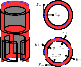
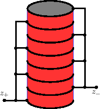
A piezo tube scanner consists of a tube of piezoelectric material sandwiched between several electrodes (Fig. 1). With this configuration, the main issue in driving piezo movement is charging the capacitor.
The time constant ![]() for charging a capacitor
for charging a capacitor ![]() in series with a resistor
in series with a resistor ![]() is given by
is given by
| (1) |
 |
(2) |
Because we expect small movements relative to the size of the piezo, we can expect that ![]() remains relatively constant, so
remains relatively constant, so ![]() will be roughly constant over our working range.
will be roughly constant over our working range.
In order to estimate the charging time for an unstretched piezo, we need to measure the capacitance of the piezo scanner.
As we do not seem to have a capacitance-measuring device in the lab, we will build one with our NI analog board[2].
There are many complicated methods of accurately measuring impedance, but it seemed simple enough to just source an alternating current and measure the voltage induced over our piezo.
For those whose E&M is rusty, the impedance of a capacitor ![]() and inductor
and inductor ![]() are given by
are given by
| (3) | ||
| (4) |
I wrote a LabVIEW VI to measure capacitance by sourcing a driving current from our NI PCI-6052E board[2], but the sampling limit at 333kHz and the leakage capacitance and resistance of my voltage measuring leads limited the measurement to larger capacitances than I had available.
I then wrote a LabVIEW VI to measure capacitance by watching the RC charging time for a capacitor and resistor in series, but again, the low impedance of the voltage-measuring leads limited the measurement to high capacitances.
I finally purchased some NE555N integrated circuits from Newark (SKU: 89K1486, $0.121), and following their suggested layout for monostable operation, generated a digital pulse with width ![]() [3].
The high impedance of the 555 chip allowed the use of the larger resistors needed for smaller capacitors.
Using meas_cap to generate the trigger pulse and measure the width of the resulting pulse, I finally got accurate measurements for my test capacitors.
Using
[3].
The high impedance of the 555 chip allowed the use of the larger resistors needed for smaller capacitors.
Using meas_cap to generate the trigger pulse and measure the width of the resulting pulse, I finally got accurate measurements for my test capacitors.
Using ![]() trials with a
trials with a
![]() resistor and a
resistor and a
![]() sampling rate, I measured my calibration capacitors at
sampling rate, I measured my calibration capacitors at
| Rated (pF) | Measured (pF) | |
| 0 | 16.7 | 0.1 |
| 390 | 425.9 | 0.1 |
| 1000 | 1008.8 | 3.0 |
| 1390 | 1413.6 | 6.0 |
With the 555 timer setup, I measured the ![]() /
/![]() /
/![]() capacitances for E- and J-type scanners, yielding the capacitances listed in Table 1.
The capacitance of stack piezos is much, much larger than tube piezos.
capacitances for E- and J-type scanners, yielding the capacitances listed in Table 1.
The capacitance of stack piezos is much, much larger than tube piezos.
The pinouts for a DI piezo module are as follows (piezo cable is female micro DB-9, labeled from upper right, 1 2 3 4 5 / 6 7 8 9)[4]:
| DB-25 Line | Piezo cable line | Color | Role |
| 8 | 1 | Black | Ground |
| - | 2 | - | Unused |
| - | 3 | - | Unused |
| 18 | 4 | Orange | (X+) |
| 5 | 5 | Yellow | (X-) |
| 22 | 6 | ?Green? | (Z+) |
| Jumper 7 | 7 | ?Blue? | Substrate voltage |
| 20 | 8 | Purple | (Y+) |
| 7 | 9 | Grey | (Y-) |
The wiring for a Piezomechanik piezo are as follows[5]:
| Line | Color | Role | |
| BNC | shield | Low voltage piezo contact | |
| BNC | pin | High voltage piezo contact | |
| Strain gauge | Red | ||
| Strain gauge | Green | ||
| Strain gauge | Black | ||
| Strain gauge | White |
We need some estimate of ![]() in order to calculate
in order to calculate ![]() .
.
![]() will either come from the internal impedance of our current source or from some external resistor to protect from excessive current.
As a limiting case, the maximum rated current for the Nanoscope piezo control lines is
will either come from the internal impedance of our current source or from some external resistor to protect from excessive current.
As a limiting case, the maximum rated current for the Nanoscope piezo control lines is ![]() and the maximum rated voltage is
and the maximum rated voltage is
![]() (Nanoscope IVa Controller Manual Rev. B, Chapter 10 ``Access to Intermediate NanoScope IVa Signals'', Table 10.2a ``Signal Access Module Connector Ratings'').
As luck would have it, the maximum rated average current for our power supply is also
(Nanoscope IVa Controller Manual Rev. B, Chapter 10 ``Access to Intermediate NanoScope IVa Signals'', Table 10.2a ``Signal Access Module Connector Ratings'').
As luck would have it, the maximum rated average current for our power supply is also
![]() .
.
A maximum current of
![]() over a voltage range of
over a voltage range of
![]() yields a minimum resistance of
yields a minimum resistance of
![]() to avoid over-current when jumping from one voltage rail to the other.
With our Piezomechanic source, the voltage range is a unipolar
to avoid over-current when jumping from one voltage rail to the other.
With our Piezomechanic source, the voltage range is a unipolar
![]() , yielding a minimum resistance of
, yielding a minimum resistance of
![]() .
However, since the
.
However, since the ![]() s are less than
s are less than ![]() , we are within the range of the ``Current Booster'',
so we can use
, we are within the range of the ``Current Booster'',
so we can use
![]() , yielding
, yielding ![]() and
and ![]() .
We use the unboosted current over
.
We use the unboosted current over ![]() to determine the Piezomechanic-sourced rail-to-rail
to determine the Piezomechanic-sourced rail-to-rail ![]() s and velocities given in Table 1.
s and velocities given in Table 1.
The J-type piezo is rated
![]() , so it has a range of
, so it has a range of
![]() [6], giving a maximum pulling speed of
[6], giving a maximum pulling speed of
![]() (Huge!).
(Huge!).
Our current high voltage supply (Piezomechanik GmbH LE 150/025) has the following characteristics[7]:
| Input: | |
| Signal: |
|
| Impedance: |
|
| Output: | |
| Voltage total: | |
| DC-Offset range: | |
| Gain: | 30 (without attenuation) |
| Peak Current: | |
| Average Current: | |
| Noise: |
This document was generated using the LaTeX2HTML translator Version 2002-2-1 (1.71)
Copyright © 1993, 1994, 1995, 1996,
Nikos Drakos,
Computer Based Learning Unit, University of Leeds.
Copyright © 1997, 1998, 1999,
Ross Moore,
Mathematics Department, Macquarie University, Sydney.
The command line arguments were:
latex2html -split 1 -white -notransparent -html_version 3.2 -t piezo_control -dir html -mkdir -noshort_extn -top_navigation -bottom_navigation -up_url ../ -up_title Papers -show_section_numbers -style '/%7Ewking/shared/style_l2h.css' main.tex
The translation was initiated by William Trevor King on 2009-08-06